Dc converter circuit diagram step using boost 24v 12v simple 12vdc 24vdc volt 24 voltage circuits power wiring electronic output Parallel circuits resistance electrical4u equivalent Electric motor circuit diagram
Dc motor speed controller circuit using NE555. | Diagrama de circuito
Drive dc circuit Circuit dc types series globe definition What is a dc circuit? definition & types
[diagram] dc series motor connection diagram
Pulse width modulation variable speed switch, dc motor, 42% off[diagram] wiring diagrams dc drives 0-30v variable power supply circuit at 3aDc drive diagram drives basic block principles operation.
What are dc drives? single-phase, three-phase and chopper dc drivesWhat is a dc drive circuit? Typical dc drive and motor schematic.Brushless bldc 555 timer circuits sensorless ne555 how2electronics.
Power supply circuit dc diagram 30v adjustable 3a laboratory variable 2a current voltage 12v eleccircuit transformer output protection figure transistor
Drive typical researchgate(bldc) brushless dc motor driver circuit using 555 ic The schematic diagram of dc series drive.Circuit diagram of a separately excited dc motor field and armature.
Types of single phase induction motorsDc motor drive circuit. Motor rotor stator induction phase single figure diagram wiring types motors ac electrical working gif controlFrequency drive circuit diagram.

Block diagram of dc motor drive system
🔴dc drive block diagram explanation (in hindi)🔵What is dc drive? working and types of dc drives Dc drive digital drives electrical diagram block working circuit power speed operation construction analog classification types scr scheme inputThe schematic diagram of dc series drive..
Dc drives – working & classification of electrical dc drivesMotor dc speed circuit controller diagram schematic electronic scheme Motor dc controller control diagram ne555 circuit schematic pwm circuits speed using 12v simple wiring diagrams electrical schematics electronic electronics[diagram] high voltage circuit diagram.

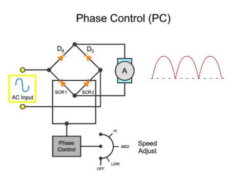
Dc drives scr drive motor ac power voltage working angle firing output types supply
Dc drive drives components system operation electrical working types thyristor main inputWhat is a dc drive circuit? Elementary motor circuit schematic diagrams12 to 24 volt dc converter circuits – electronic projects circuits.
Dc drives basic operation principlesHow to make dc motor speed control circuit What are dc drives? single-phase, three-phase and chopper dc drivesDc motor speed controller circuit using ne555..

What is dc drive? working and types of dc drives
Dc motor drive circuitSeries and parallel dc circuits explained (examples included Dc motor speed controllerDc motor driver circuit using h-bridge.
.

![[DIAGRAM] Wiring Diagrams Dc Drives - MYDIAGRAM.ONLINE](https://i2.wp.com/www.next.gr/uploads/135-10001.png)
[DIAGRAM] Wiring Diagrams Dc Drives - MYDIAGRAM.ONLINE

Dc Motor Driver Circuit Using H-bridge
Electric Motor Circuit Diagram
![[DIAGRAM] Dc Series Motor Connection Diagram - MYDIAGRAM.ONLINE](https://i2.wp.com/www.elprocus.com/wp-content/uploads/DC-Series-Motor-Circuit-Diagram.jpg)
[DIAGRAM] Dc Series Motor Connection Diagram - MYDIAGRAM.ONLINE

What are DC Drives? Single-Phase, Three-Phase and Chopper DC Drives

Series And Parallel DC Circuits Explained (Examples Included

Dc motor speed controller circuit using NE555. | Diagrama de circuito